Separation of concerns: High-level autonomy vs Low-level real-time control
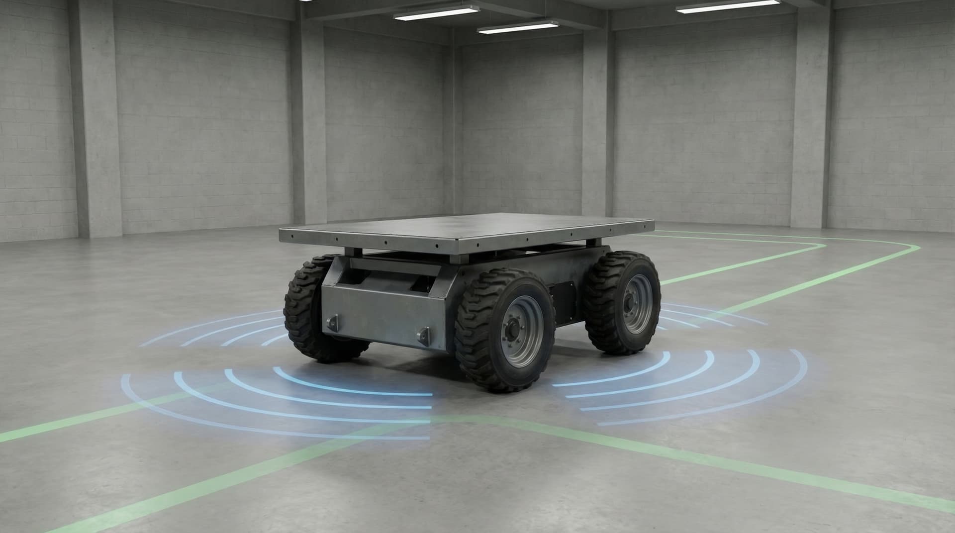
An industrial mobile robot architecture must be bifurcated into two distinct layers:
1. Real-Time Execution Layer (Microcontroller): Handled by a 32-bit MCU (such as an STM32F4/G4 or ESP32-S3). This layer runs deterministic hardware timers at 100 Hz to 1 kHz, capturing quadrature encoder pulses via hardware timer encoder modes, computing closed-loop PID/feedforward velocity control for brushless DC (BLDC) motor drivers, reading optical bumper switches, and managing emergency-stop (E-Stop) hardware cutoffs.
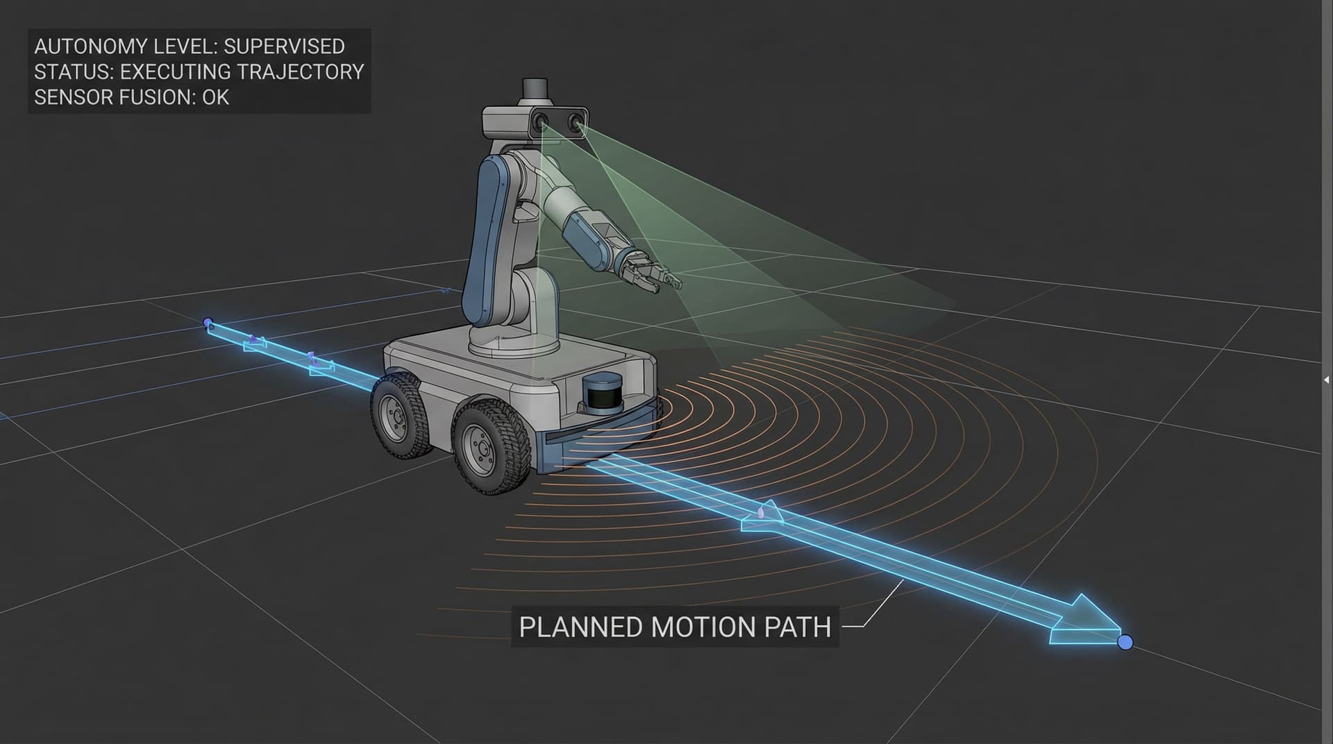
2. Autonomy & Compute Layer (Host SBC): Handled by an NVIDIA Jetson Orin Nano, Raspberry Pi CM4, or industrial x86 PC running Ubuntu 24.04 and ROS 2 Jazzy or Humble. This layer processes high-bandwidth sensor data: 2D/3D LiDAR point clouds, stereo depth camera streams, Cartographer / Slam Toolbox scan matching, global and local path planning (Nav2), and fleet management interfaces, as detailed in our Robotics Engineering & Autonomous Systems Services.
Micro-ROS vs Serial packet bridges on STM32 / ESP32
To connect the MCU to the ROS 2 host, engineers historically wrote custom serial string parsers or used legacy rosserial. In modern ROS 2 deployments, two robust approaches dominate:
• micro-ROS Client: Runs directly on bare-metal or FreeRTOS on STM32/ESP32. It natively publishes ROS 2 messages (e.g., nav_msgs/msg/Odometry, sensor_msgs/msg/Imu) and subscribes to geometry_msgs/msg/Twist (cmd_vel) over a micro-ROS Agent bridge running on the Linux host. It provides native DDS types and QoS reliability profiles.
• Binary Packet Protocol over CAN Bus or UART with DMA: For high-noise industrial chassis, running a dedicated CAN 2.0B or CAN-FD bus at 500 kbps / 1 Mbps between motor controllers and a central MCU provides superior noise immunity and multi-drop wiring. The MCU then aggregates telemetry and communicates with the Linux host via high-speed UART (921,600 baud) using DMA buffers and CRC16 checksum verification.
Odometry pipeline: Encoders, IMU fusion, and the robot_localization EKF
Accurate dead reckoning is the foundation of reliable autonomous navigation. In a differential drive or mecanum mobile base, relying solely on wheel optical encoders introduces cumulative drift: wheel slip during sudden deceleration, tire compliance under payload changes, and floor irregularities corrupt the robot's pose estimate.
The industry standard pipeline uses the ROS 2 robot_localization package running an Extended Kalman Filter (EKF): • Source 1: Wheel odometry from the MCU (linear velocity vx, angular velocity vtheta). • Source 2: 6-DOF IMU mounted rigidly along the robot's center of gravity (yaw velocity wz and linear accelerations ax, ay). The EKF fuses high-rate wheel encoders (accurate short-term translation) with the IMU gyro (immune to wheel slip during rapid turns), publishing a drift-reduced odom -> base_link transform that allows Nav2 costmaps to remain crisp and stable during high-speed transit, as deployed in our 80kg-Payload Heavy AMR Platform Development Case Study.
Power distribution and electrical noise isolation for mobile bases
High-current motor transients are the primary culprit behind unexplained SBC reboots and sensor data corruption on mobile robots. When an 80kg AMR accelerates from rest or encounters an obstacle, peak motor current can surge to 30A–50A within milliseconds, causing battery bus voltage sag (inductive kick and internal battery IR drop).
Key electrical design practices: 1. Separate battery rails: Step down 24V or 48V LiFePO4 battery voltage through an isolated, wide-input DC-DC converter (e.g., 18V–75V input to regulated 12V / 5V) specifically dedicated to compute and sensors, with large bulk electrolytic reservoir capacitors. 2. Galvanic ground isolation: Route motor return currents directly back to the battery BMS terminal via star grounding to avoid sharing high-current motor ground paths with sensitive analog IMU or micro-ROS UART return paths. 3. Hardware E-Stop safety loop: The emergency stop button must physically de-energize the motor driver gate power or drop the main DC contactor coil through dual-channel safety relays, rather than relying solely on software stop commands.
Sensor topology: 2D/3D LiDAR, depth cameras, and wheel base placement
Mounting sensors correctly on the mechanical CAD frame is critical before running SLAM:
• 2D Safety / Navigation LiDAR: Positioned at 150mm–250mm above floor level to detect low obstacles, pallet feet, and walls. If positioned too high, low obstacles fall into the blind spot below the scan plane; if too low, floor tilt during acceleration causes ground plane false positives. For 360-degree coverage, either mount on opposing diagonal corners (front-left and rear-right dual LiDARs merged via laser_filters) or use an elevated mast.
• RGB-D Depth Cameras: Mounted forward-facing at a slight downward angle (15°–20°) to detect drop-offs (negative obstacles like stairwells or loading docks) and overhangs (tabletops, warehouse pallet rack beams) that pass over the 2D LiDAR plane.
• Kinematic Center Alignment: Ensure the robot's physical wheel axle center coincides accurately with the base_link frame origin in the URDF CAD description to avoid kinematic calculation errors.
Common hardware integration failures in mobile robotics prototyping
1. Using non-real-time USB-to-UART dongles: Cheap FTDI or CH340 USB serial adapters have kernel buffer latency timers (typically defaulting to 16ms in Linux). Set latency_timer to 1ms in udev rules or use native hardware serial (/dev/ttyTHS* or /dev/ttyAMA*) to avoid sluggish control loop feedback.
2. Lack of hardware quadrature decoding: Decoding high-resolution 1024-PPR encoders using software GPIO pin-change interrupts can overload the MCU at high motor RPM. Using dedicated microcontroller hardware timer peripheral encoder modes prevents missed counts.
3. Back-EMF energy return during braking: When decelerating a heavy robot carrying its payload, motors act as generators, dumping current back into the power bus. Without regenerative braking management or TVS clamp diodes, the bus voltage spikes, destroying motor driver MOSFETs.
4. Loose mechanical sensor fixtures: A 3D printed LiDAR mount that flexes by even 0.5 degrees under chassis vibration causes point cloud oscillation, manifesting as false 'phantom obstacles' in Nav2 local costmaps.