Mechanical Design & CAD

Mechanical CAD & Product Development

YantriX provides engineering-led mechanical CAD and product development from our studio in Surat, India. We partner remotely with hardware startups, industrial manufacturers, and engineering teams worldwide to build fully parametric, DFM-optimized CAD models and 2D manufacturing drawings prepared using ASME Y14.5 GD&T practices.

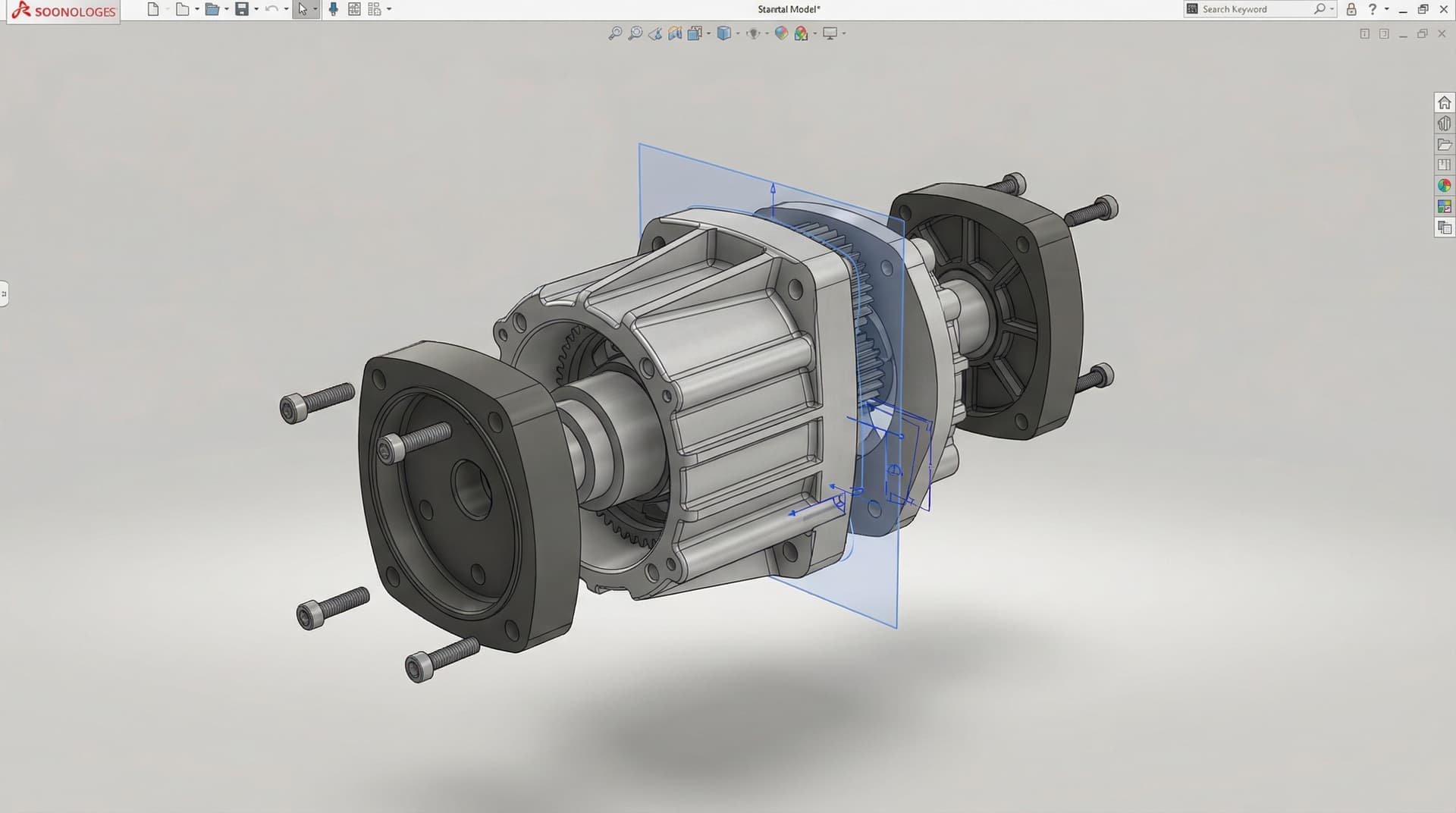
CAD design services in India — parametric SolidWorks modeling at YantriX studio

What we do

Practical support for targeted engineering work

We deliver end-to-end CAD design services in India: parametric 3D modeling in SolidWorks and Fusion 360, surface modeling for consumer products, sheet metal design with K-factor calculations and flat-pattern drawings, plastic injection molding parts (draft, parting lines, shrinkage compensation), DFM (Design for Manufacturing) review of existing designs, reverse engineering from physical samples or 2D drawings, and 2D production drawings (GD&T, tolerances, BOM, manufacturing notes) for vendor handoff. We support client teams at every stage from sketch through tooling release.

What problems we solve

  • Reduce redesign and rework caused by poor manufacturability decisions caught only at the vendor stage.
  • Convert physical samples or hand sketches into structured parametric CAD that downstream teams can iterate on.
  • Translate design intent into 2D production drawings with proper GD&T that manufacturers worldwide can quote and produce reliably.
  • Build sheet metal enclosures with K-factor calculations and flat patterns ready for the press brake.
  • DFM-review existing CAD before tooling release to catch issues that would cost weeks of mold rework later.

Tools we use

  • SolidWorks — primary parametric modeling and assemblies
  • Fusion 360 — secondary CAD and design-for-additive workflows
  • AutoCAD — 2D drawings and legacy file support
  • KeyShot — photorealistic rendering for client presentations
  • DraftSight, LibreCAD — 2D drawing tools
  • GD&T per ASME Y14.5 — geometric dimensioning and tolerancing
  • DFM checklists tuned for injection molding, sheet metal, and CNC machining
  • STEP / IGES / Parasolid — neutral-format CAD interchange

Deliverables

  • 3D parametric CAD models (SolidWorks .sldprt / .sldasm or Fusion 360 archive)
  • Neutral-format files for vendor handoff (STEP, IGES, Parasolid)
  • 2D production drawings prepared using ASME Y14.5 GD&T practices, with tolerances, surface finishes, and notes
  • Bill of Materials (BOM) with vendor recommendations
  • Sheet metal flat patterns (DXF) ready for the press brake or laser cutter
  • Plastic injection molding feasibility report — draft, parting line, gate location, shrinkage
  • Reverse engineering CAD from physical samples or 2D drawings
  • Photorealistic renders for client presentations and pitch decks

Have a project requiring this engineering scope?

Share your technical requirements, 3D CAD files, or operating specs. NDA support is available where required before confidential file exchange.

Discuss Your CAD Project
Use cases

Industries where this service applies

We adapt the same engineering service to different product contexts depending on the load case, packaging problem, validation target, or deployment environment.

Consumer product design

Ergonomic handheld housings, snap-fit assemblies, cosmetic CMF surfacing, and split-line architectures ready for high-volume tooling.

Industrial machinery and equipment

Mechanical frames, guards, motor mounts, sensor brackets, machine enclosures, and assemblies designed around manufacturability, access, and maintenance.

Sheet metal enclosures and chassis

Precision 19-inch rack enclosures, DIN-rail chassis, K-factor bend relief, and PEM hardware integration ready for CNC turret and laser fab.

Plastic injection molded parts

Tooling-ready plastic components with uniform 2.5mm wall coring, 1.5° draft angles, optimized gate locations, and moldflow sink elimination.

Automotive aftermarket and motorsport

High-strength suspension brackets, fluid cooling manifolds, intake geometries, and lightweight chassis members validated via structural FEA.

Robotics and automation hardware

Cycloidal joint packages, harmonic drive brackets, AMR skid-steer chassis, sensor towers, and custom end-effector gripper mechanisms.

Medical devices and lab equipment (non-implant)

Fluidic manifold blocks, precision pipette arms, sterilization-compatible housings, and ergonomic benchtop diagnostic enclosures.

IoT and smart-home hardware

IP67/IP68 sealed enclosures, captive O-ring channels, antenna-transparent window geometry, and thermal potting reservoirs.

Related work

Case studies tied to this service

See how this engineering capability applies across real project scopes, analysis goals, and physical prototype iterations.

CAD Design · Mechanical & DFM

DFM Architecture & Injection Mold Optimization for IP67 IoT Enclosure

Complete CAD design and DFM optimization for a multi-part outdoor IoT enclosure in polycarbonate — 1.5° uniform draft, overmolded silicone gasket, and moldflow sink-mark elimination.

CAD Design · Sheet Metal & Enclosures

Sheet Metal Industrial Inverter Enclosure CAD & DFM Optimization

Parametric CAD design for an industrial solar inverter enclosure — K-factor bend deduction, PEM hardware spacing, thermal louvers, and flat-pattern DXF export.

Robotics · Mechanical Design

6-DOF Teleoperated Robotic Arm Mechanical Architecture & Kinematics

Mechanical design of a 6-DOF compact robotic arm with cycloidal gearboxes hitting ±0.1 mm repeatability at 5 kg payload — from kinematic chain to manufactured prototype.

From the blog

Articles that support this service topic

Explore practical engineering guides covering CAD modeling, sheet metal design, injection molding DFM, and tooling.

Mechanical Design

STEP vs IGES vs Parasolid: CAD File Formats for Manufacturing Handoff

A practical engineering guide comparing STEP (AP203, AP214, AP242), IGES, and Parasolid (X_T) for CNC machining, injection molding, sheet metal, and vendor quoting.

Mechanical Design

DFM Checklist for Indian Manufacturing: Catch These Issues Before Tooling

A practical Design-for-Manufacturing checklist tuned for Indian vendors — injection molding, sheet metal, CNC machining, and 3D printing. The issues we catch in pre-tooling DFM review every week.

Mechanical Design

Sheet Metal CAD Design in India: K-Factor, Bend Allowance, and Production-Ready Drawings

How to do sheet metal CAD design that Indian press brake vendors can actually produce — K-factor calculations, bend allowance, gauge selection, and the production drawing workflow that prevents rework.

FAQ

Questions teams ask before they engage

Common questions teams ask before starting a project.

What CAD design and product development services do you offer?

Parametric 3D modeling (SolidWorks, Fusion 360), surface modeling, sheet metal design with K-factor, plastic injection molding parts, DFM review, reverse engineering from physical samples, and 2D manufacturing drawings prepared using ASME Y14.5 GD&T practices. We support consumer products, industrial machinery, robotics hardware, and automotive applications.

Can you start from a sketch, photo, or physical sample?

Yes. We routinely build parametric CAD from hand sketches, marked-up photos, scanned 2D drawings, or physical samples. For physical samples, we use calipers and precision measurement tooling.

Do you provide DFM review for existing CAD?

Yes. DFM review is one of our most-requested services. We review the CAD against the intended manufacturing process (injection molding, sheet metal, CNC, 3D printing) and flag issues before tooling release. Output is an annotated report with CAD screenshots and specific fix recommendations.

Which CAD software do you work in?

SolidWorks is our primary tool for parametric assemblies and manufacturing drawings. Fusion 360 is our secondary tool for additive design. We deliver in your preferred native format or in neutral STEP / IGES / Parasolid formats.

How much do CAD design services cost?

Pricing is scoped transparently based on complexity: simple parametric parts start at ₹3,000–₹15,000 ($40–$180 USD), complex multi-part assemblies at ₹15,000–₹60,000 ($180–$750 USD), and complete product development programs with DFM and 2D manufacturing drawings at ₹50,000+ ($600+ USD). We provide itemized quotes following project scoping.

Do you provide 2D production drawings with GD&T?

Yes. 2D manufacturing drawings prepared using ASME Y14.5 GD&T practices are part of our standard deliverable. We calibrate tolerances to the realistic capability of target manufacturing processes so drawings can be quoted and fabricated without ambiguity.

Can you sign NDA for confidential product design?

Yes. Mutual NDA available before confidential CAD/IP exchange. We routinely sign your template or ours upon request.

Start your project

Have a Product You Need Designed? Discuss Your CAD Project

From napkin sketches to complex mechanical assemblies, send us your requirements. We'll review manufacturability, provide NDA support where required, and define the CAD scope.