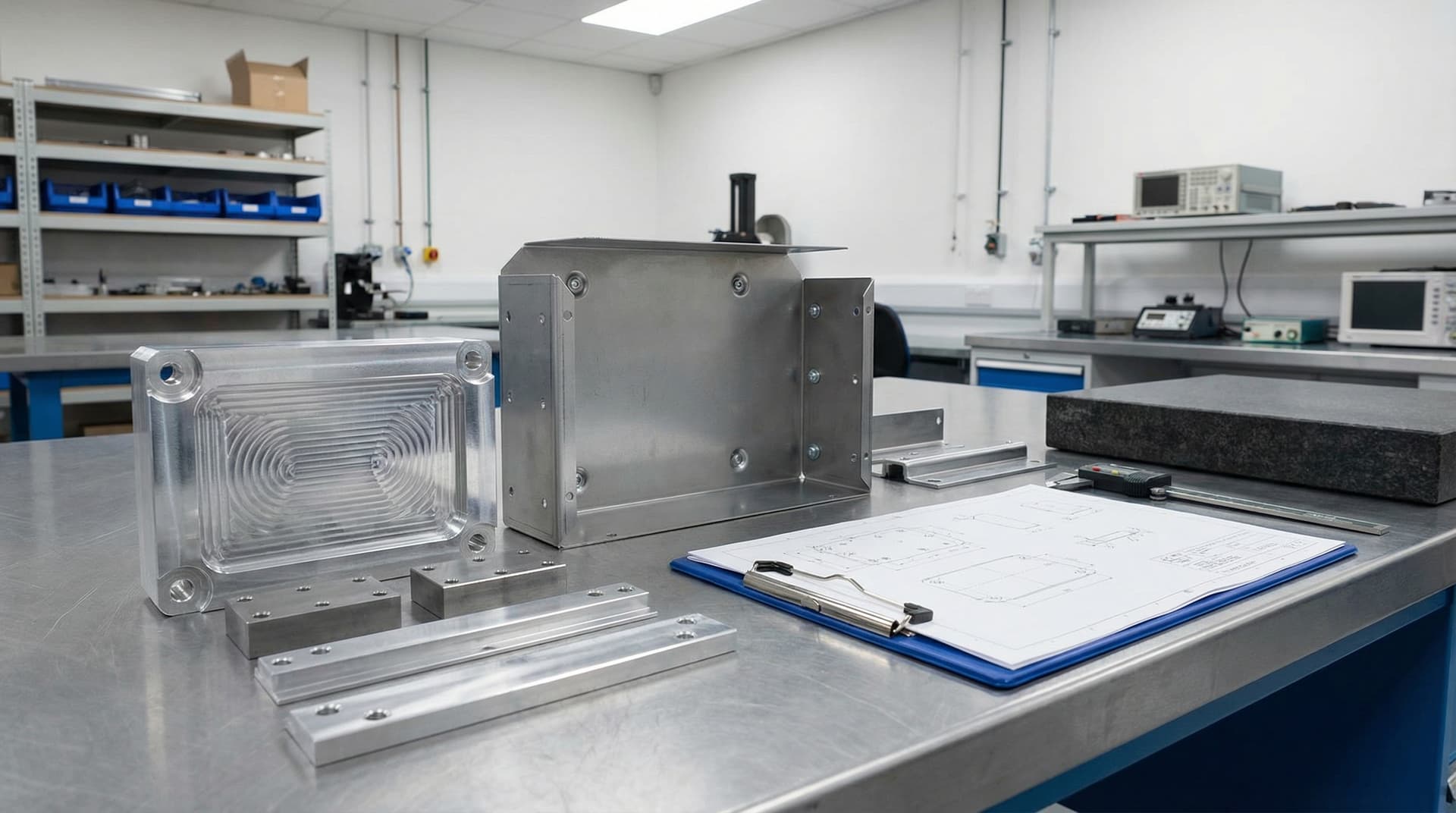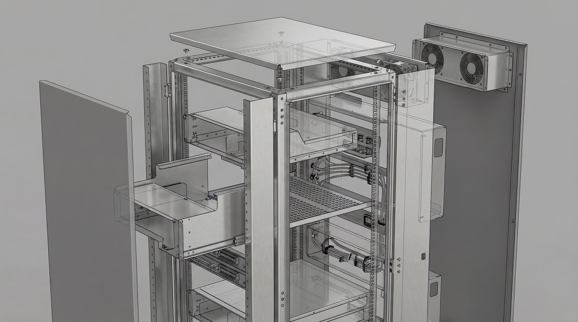

Precision Sheet Metal Enclosure CAD Design with K-Factor & DFM Optimization, case study.
An industrial power electronics OEM required a rugged sheet metal enclosure designed for CNC turret punch and press brake fabrication. Yantrix delivered the complete parametric SolidWorks CAD, K-factor verified flat patterns, structural gussets, and ASME Y14.5 fabrication drawings.

Overview
Why this study matters
Parametric CAD design for an industrial solar inverter enclosure — K-factor bend deduction, PEM hardware spacing, thermal louvers, and flat-pattern DXF export.
Client: An Indian power electronics manufacturer building outdoor solar string inverters
Project Type: Sheet Metal CAD Design + DFM + Production Drawings
Industry: Power Electronics & Renewable Energy
Service Used: CAD Design & DFM + Sheet Metal Flat Patterns + 2D Drawings
Results in numbers
What the engagement actually shipped.
- IP55
- Weatherproof ingress design
- 2.0 mm
- CRCA steel chassis
- 45 kg
- Rated structural load
- DXF
- Flat pattern laser files
Objectives
What the project needed to achieve
- Design a 2.0 mm CRCA steel and aluminum chassis supporting 45 kg internal component load
- Calculate precise K-factors and bend deductions matched to Indian press brake tooling
- Incorporate rain-hood louvers and labyrinth airflow baffles for IP55 ingress protection
- Deliver 1:1 DXF flat patterns and ASME Y14.5 production drawings with fastener torque callouts
Challenge
Engineering constraint
The client needed a weather-resistant (IP55) sheet metal enclosure capable of housing a 50 kW inverter sub-assembly with heavy magnetics (35 kg transformers). Previous vendor CAD files lacked bend deduction calculations and suffered from hole deformation near bend lines and weld distortion on cosmetic outer panels.
Approach
How Yantrix approached the work
- 01Constructed master parametric sheet metal model in SolidWorks with global variables for material thickness and tooling bend radius.
- 02Engineered corner relief cutouts and tear reliefs to prevent tearing during air bending on CNC press brakes.
- 03Positioned PEM clinch nuts and studs with required edge-to-bend clearance zones (min 2.5× sheet thickness).
- 04Designed staggered rain-hood ventilation louvers with internal mesh filters for IP55 weather sealing.
- 05Generated nested flat pattern DXFs with bend line notes (up/down angles and tool radius) for fiber laser cutting.
Outcomes
What improved by the end
- First-article sheet metal prototype assembled with zero hole reaming or panel misalignment
- 45 kg internal structural loading validated with under 0.8 mm max chassis deflection
- Toolmaker achieved 100% first-pass bend accuracy directly from exported DXF flat patterns
- Unit fabrication cycle time reduced by ~20% via simplified single-setup bend sequences
Deliverables
What the client receives
- Parametric SolidWorks sheet metal assembly and individual part models (.sldprt / .sldasm)
- 1:1 scaled DXF flat patterns with bend annotations for CNC laser and press brake
- Complete ASME Y14.5 production drawings with weld symbols and powder coat callouts
- Structural load FEA report for seismic and transport vibration
Tools used
Stack and tooling
- SolidWorks Sheet Metal
- AutoCAD for DXF validation
- ANSYS Mechanical (gravity and seismic load FEA)
- ASME Y14.5-2018 GD&T Standards
Impact
Business-level effect
- Saved 4 weeks of prototyping by eliminating manual sheet metal shop-floor adjustments
- Standardized K-factor tables across the client's vendor network for repeatable fabrication
Conclusion
Sheet metal CAD only delivers speed when bend mechanics, tooling radii, and PEM hardware clearances are baked into the 3D model before cutting laser sheet.
Next step
Need sheet metal enclosures, brackets, or machine frames engineered for laser cutting and press brake forming? Send us your packaging requirements for a DFM review.
Tagged
- Sheet Metal
- SolidWorks
- DFM
- K-Factor
- CAD Design
- Enclosure
Visual results
Key views and intermediate artefacts


Louver and labyrinth baffle CAD
Frequently asked questions
Answers from the engagement itself.
What K-factor do you use for sheet metal CAD?
We tune K-factor per material and vendor tooling — typically 0.44 to 0.48 for mild steel and 0.40 to 0.42 for aluminium air-bending. If your vendor has specific deduction charts, we bake their exact numbers into the CAD master model.
Can you provide flat patterns ready for laser cutting?
Yes. We deliver 1:1 DXF flat patterns with bend centerlines, direction (up/down), and bend angles clearly annotated on dedicated layers.
Related case studies
Adjacent proof you can read next.

CAD Design · Mechanical & DFM
DFM Redesign & Injection Mold Optimization for IP67 IoT Enclosure
Complete CAD design and DFM optimization for a multi-part outdoor IoT enclosure in polycarbonate — 1.5° uniform draft, overmolded silicone gasket, and moldflow sink-mark elimination.

ML-accelerated engineering
500× faster topology exploration with an ML-surrogate FEA
A physics-informed neural network trained on 12,000 ANSYS runs replaces the full solver for early-stage topology — predicts stress fields in 40 ms vs. 22-minute solves.
Continue exploring
Related blogs, services, and capability pages
Cross-links help readers move from proof into capability and educational content, and they reinforce the crawl path between commercial pages and reference content.
Have a machine to build? Let's scope it together.
Tell us about your project. We'll respond within 1-2 business days with a preliminary scope and timeline — no boilerplate, no up-sell.