The underlying geometry: Solid B-Rep vs Surface Wireframe
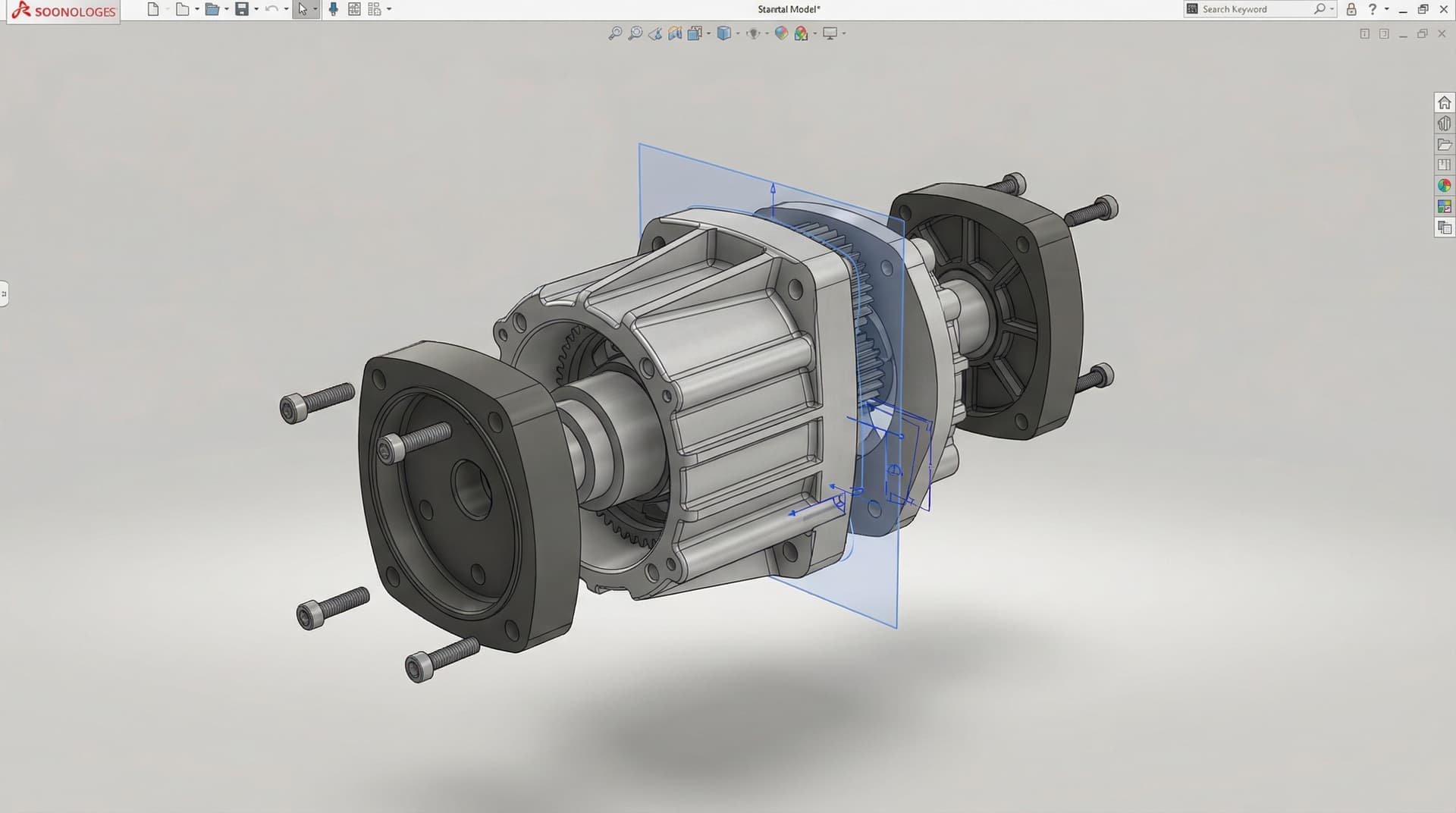
The core difference between CAD formats lies in how geometry is mathematically stored. Parasolid and modern STEP files store solid bodies as Boundary Representations (B-Rep). A B-Rep model defines closed, watertight topological volumes bounded by faces, edges, and vertices, maintaining exact analytic curvatures (cylinders, planes, tori, NURBS). In contrast, legacy formats like IGES treat geometry as an unstitched collection of independent trimmed surfaces and wireframe curves with no topological understanding of what is 'inside' or 'outside' the solid body.
When a CAM programmer imports an IGES file, the software must attempt to stitch adjacent surface edges within a user-defined tolerance. If the originating CAD exported tolerances differ from the CAM import threshold, microscopic gaps (0.01mm to 0.05mm) appear between surfaces. Toolpath generation algorithms either fail at these slivers or generate gouging tool trajectories.
STEP AP203 vs AP214 vs AP242: Which protocol should you export?
STEP (ISO 10303) is the universal neutral CAD exchange standard, but exporting simply as 'STEP' without checking the Application Protocol (AP) leads to lost metadata:
• STEP AP203: The original 1994 configuration. It captures solid 3D geometry and assembly structure cleanly, but strips out all surface colors, layer organizations, and manufacturing annotations. It is universally supported but primitive.
• STEP AP214: The automotive standard introduced in 2001. It retains everything in AP203 plus face and body colors, geometric tolerances, surface finish callouts, and multi-body assembly hierarchies. In our Mechanical CAD & Product Development Services, AP214 has historically been the reliable default for standard CNC and mold quotes.
• STEP AP242: The modern unified standard (combining AP203 and AP214). AP242 includes full semantic 3D Model-Based Definition (MBD) and Product and Manufacturing Information (PMI). Geometric Dimensioning & Tolerancing (GD&T), datum reference frames, thread specifications, and notes are embedded directly into the 3D geometry, eliminating reliance on standalone 2D PDF drawings for automated coordinate-measuring machine (CMM) inspection.
Parasolid (.x_t / .x_b): When kernel-level handoff is advantageous
If your engineering team uses SolidWorks, Siemens NX, Onshape, or Solid Edge, the underlying geometric engine is the Siemens Parasolid modeling kernel. Several industrial CAM packages (Mastercam, GibbsCAM, hyperMILL, CAMWorks) can also import and process Parasolid data natively.
When both the source CAD tool and the receiving CAM system use the Parasolid kernel, exporting as Parasolid Text (.x_t) or Parasolid Binary (.x_b) enables a direct, kernel-level geometric transfer. This significantly reduces translation tolerances and minimizes surface slivers compared with older neutral formats. However, compatibility depends on receiving software versions and kernel alignment. STEP remains the universal neutral standard across disparate systems, but where Parasolid pipelines align, supplying an .x_t file alongside production drawings provides a very reliable handoff.
Why IGES causes surface stitching failures in CNC and tooling
The Initial Graphics Exchange Specification (IGES) was standardized by the US Air Force in 1980 — before modern solid modeling existed. Because IGES does not store topological connectivity between adjacent faces, exporting a molded plastic housing like the one in our IP67 IoT Enclosure Injection Molding & DFM Case Study into IGES breaks the part into hundreds of detached trimmed surface patches.
Tooling engineers must manually heal and stitch these patches in their CAM software before they can calculate electric discharge machining (EDM) electrodes or core/cavity split lines. This manual healing introduces human error and delays quoting by days. IGES should only be used if an ancient wire EDM machine or legacy CMM controller cannot parse STEP.
Common export mistakes that break vendor CAM workflows
1. Exporting assemblies as single merged parts: When releasing a multi-part sheet metal enclosure or robot bracket assembly, exporting as an unpartitioned single body forces the fabricator to manually dissect components. Always maintain assembly hierarchy.
2. Selecting coarse chordal tolerance during STEP export: SolidWorks and Creo allow customizable chordal tessellation tolerances. If set too loose, circular holes and cylindrical bores export with chordal faceting that distorts toolpath compensation.
3. Sending STL files for subtractive machining: STL converts all smooth analytic surfaces into planar triangular facets. A 25.00mm H7 precision bearing bore becomes a polygon of dozens of microscopic flats, rendering CNC circular interpolation impossible.
4. Stripping coordinate origins: Ensure the model's global origin (WCS) is located logically on a flat locating datum or mounting face rather than floating in arbitrary space, especially for sheet metal parts discussed in our Sheet Metal Inverter Enclosure CAD Case Study.
The recommended manufacturing handoff package
When releasing hardware designs to vendors, YantriX recommends supplying a structured handoff package:
1. Universal STEP AP242 (or AP214): The primary neutral exchange standard, ensuring robust solid geometry compatibility across virtually all CAD and CAM packages.
2. Parasolid (.x_t): When the vendor's CAM environment natively supports Parasolid, to further reduce geometric translation steps.
3. Fully Dimensioned 2D PDF Drawing: Prepared strictly to ASME Y14.5 practices, specifying material callouts, heat treatments, surface finishes, inspection dimensions, and critical GD&T feature control frames.
4. Engineering BOM & Inspection Table: Listing hardware part numbers, quantities, thread sizes, and critical inspection points.