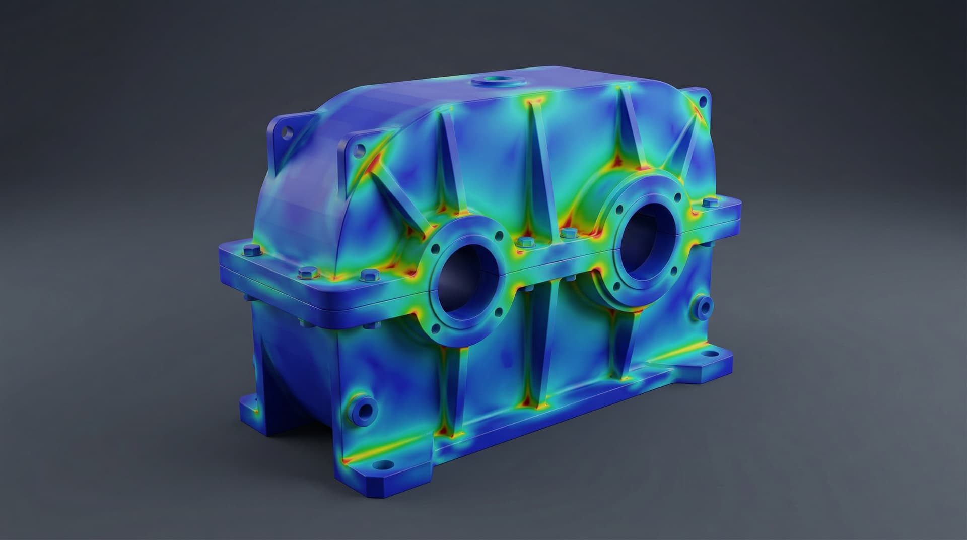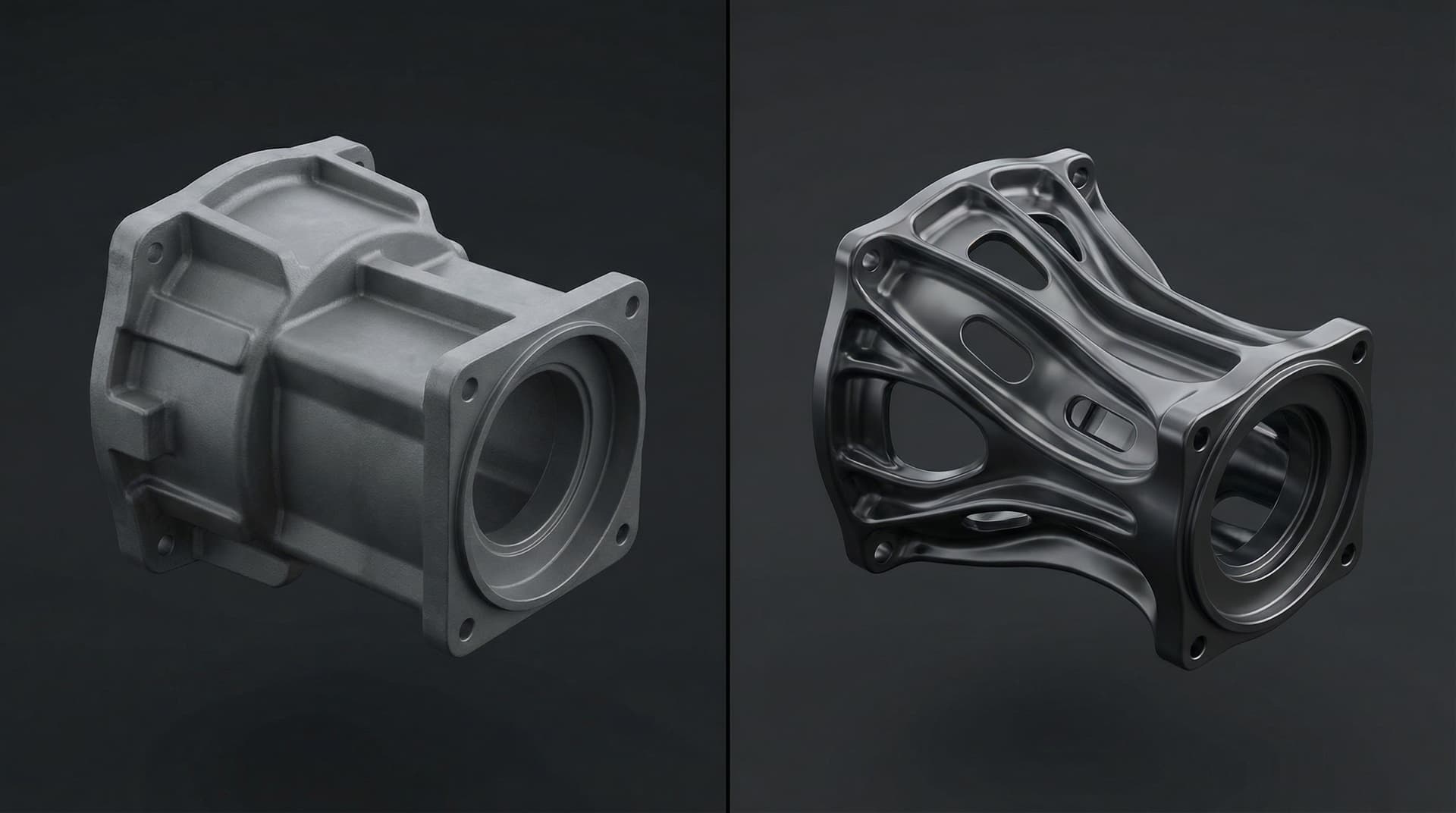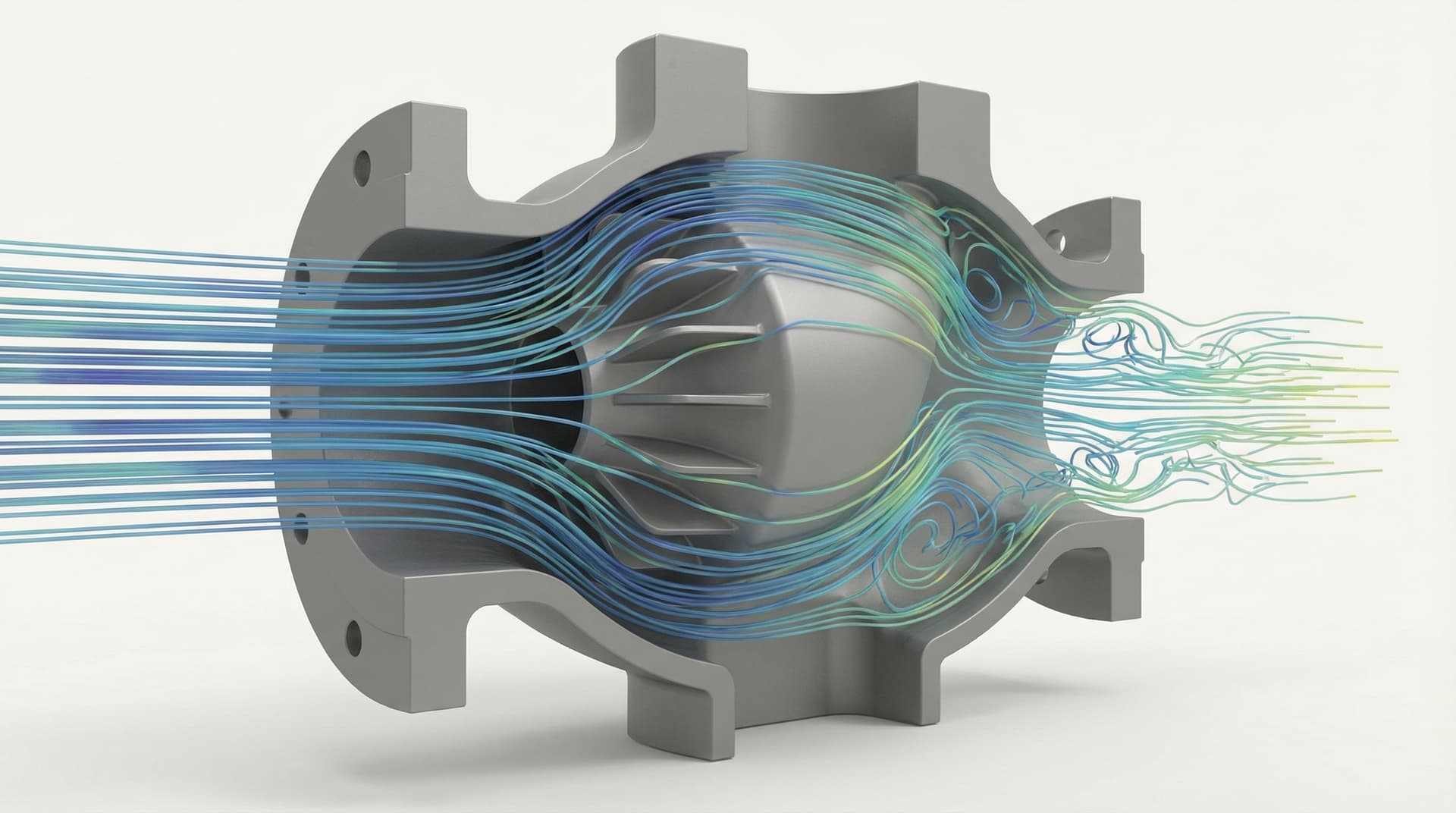
Understanding Von Mises stress: Distortion energy vs Principal stress
Most structural FEA reports prominently feature Von Mises stress contours. But what does Von Mises stress actually represent? According to the maximum distortion energy theory, yielding in a ductile material begins when the distortion strain energy per unit volume equals the distortion strain energy at yield in simple tension.
Von Mises combines the three-dimensional normal and shear stress components (σx, σy, σz, τxy, τyz, τzx) into a single scalar equivalent stress value. It works exceptionally well for structural steel, 6061-T6 aluminum, and ductile engineering plastics. However, for brittle materials (cast iron, highly filled composites, brittle resins), Von Mises is generally not the governing criterion; brittle materials typically fail due to normal tensile fracture rather than shear slip, requiring evaluation against Maximum Principal Stress (Rankine criterion) or Mohr-Coulomb criteria. In our FEA Analysis & Structural Simulation Services, we select the failure theory matching the specific material constitutive model.
The stress singularity trap: Sharp corners, point loads, and boundary restraints
One of the most frequent causes of misinterpreting FEA results is the mathematical stress singularity. In elasticity theory, the stress at an infinitely sharp internal 90-degree re-entrant corner is theoretically infinite. In a finite element model with a sharp re-entrant corner, refining the element mesh smaller and smaller causes the calculated stress to continually climb without bound (e.g., 200 MPa → 450 MPa → 900 MPa).
If an inexperienced engineer sees this red spike, they might unnecessarily thicken the entire structure or declare the design unusable. In reality, physical manufacturing always introduces a cutting tool radius (e.g., 0.5mm corner radius on an end mill or 0.2mm edge break). Replacing the mathematical sharp corner in CAD with the true manufacturing fillet radius converts the singularity into a legitimate stress concentration (Kt) that converges cleanly under mesh refinement.
How to conduct a valid mesh convergence study
A single FEA run without mesh verification provides limited confidence. The finite element method approximates a continuous displacement field using discrete polynomial element shapes. If the mesh is too coarse, the elements artificially stiffen the structure, underpredicting deflections and peak stresses.
A rigorous mesh convergence protocol requires: 1. Baseline solve with global element size h. 2. Localized mesh refinement: Apply an element size of h/2 to critical stress gradient zones (fillets, bolt holes, notch transitions). 3. Quadratic elements: Use second-order tetrahedral (10-node) or hexahedral (20-node) elements rather than stiff linear 4-node tets. 4. Compare metrics: Calculate the percentage change in peak Von Mises stress and maximum displacement: [Stress(h/2) - Stress(h)] / Stress(h/2). When the change between successive refinements falls below 3% to 5%, the solution has converged and is independent of the mesh discretization, as demonstrated in our Structural Failure Reduction FEA Simulation Case Study.
Yield criteria vs Ultimate tensile failure in structural polymers and metals
Interpreting the Factor of Safety (FoS = Material Strength / Calculated Stress) requires defining which material threshold governs design survival:
• Yield Factor of Safety (FoS_yield = Sy / σ_max): Ensures that the component operates strictly within its elastic regime. For structural brackets, robotic actuator arms, and precision optical mounts, plastic deformation means permanent dimensional loss and functional failure. A minimum FoS_yield of 1.5 to 2.0 is standard in industrial hardware.
• Ultimate Factor of Safety (FoS_ultimate = Sut / σ_max): Evaluates the margin against complete physical separation or catastrophic fracture. In pressure vessels, lifting lugs, and drone airframes explored in our 6-DOF Robotic Arm Mechanical Architecture, transient shock loads may cause local micro-yielding without causing ultimate rupture.
Common FEA interpretation errors in product development
1. Over-constraining rigid fixtures: Pinning all degrees of freedom (Ux=Uy=Uz=0) across a broad face artificially prevents Poisson contraction, generating false reaction stresses at the boundary edges. Use soft springs, frictionless supports, or bolted joint preloads.
2. Applying concentrated point loads: Real forces never apply across a single infinitely small mathematical node. Distribute loads across the true contact bearing area or use RBE3 distributed coupling spiders.
3. Ignoring nonlinear contact dynamics: Assuming bonded contacts between bolted plates masks micro-slipping and contact pressure distribution. For high-load assemblies, nonlinear surface-to-surface contact with friction is required.
4. Confusing displacement scale with real deformation: FEA post-processors default to 5× or 100× exaggerated deformation display so deflection modes are visually apparent. Always verify the true numeric millimeter deflection before alarming design stakeholders.
Engineering best practices for simulation-driven design validation
To ensure simulation results reliably predict physical hardware performance:
1. Establish explicit acceptance criteria before running the solver (e.g., maximum permissible deflection of 0.25mm under full rated payload, minimum FoS of 2.0 against yield). 2. Document material certified mill test reports (MTR) or polymer tensile datasheets, paying attention to temperature derating (yield strength drops significantly as operating temperature rises). 3. Perform sanity checks against closed-form analytical beam equations (Roark's Formulas for Stress and Strain) before trusting multi-body assemblies. 4. Close the loop with bench testing: Compare simulated strain gauge or dial indicator readings against physical prototype validation.