Simulation

Thermal analysis for electronics enclosures: CFD, CHT & Heat Dissipation Guide, explained simply.

Thermal behavior is one of the hardest characteristics to retrofit in hardware. When teams wait until physical prototype testing to discover heat bottlenecks, fixing hotspots requires tooling revisions, altered PCB layouts, and weeks of project delays. This guide breaks down how CFD-based thermal analysis validates electronics packaging during the CAD stage.

By YantriX Engineering Team · Simulation Studio3 min read
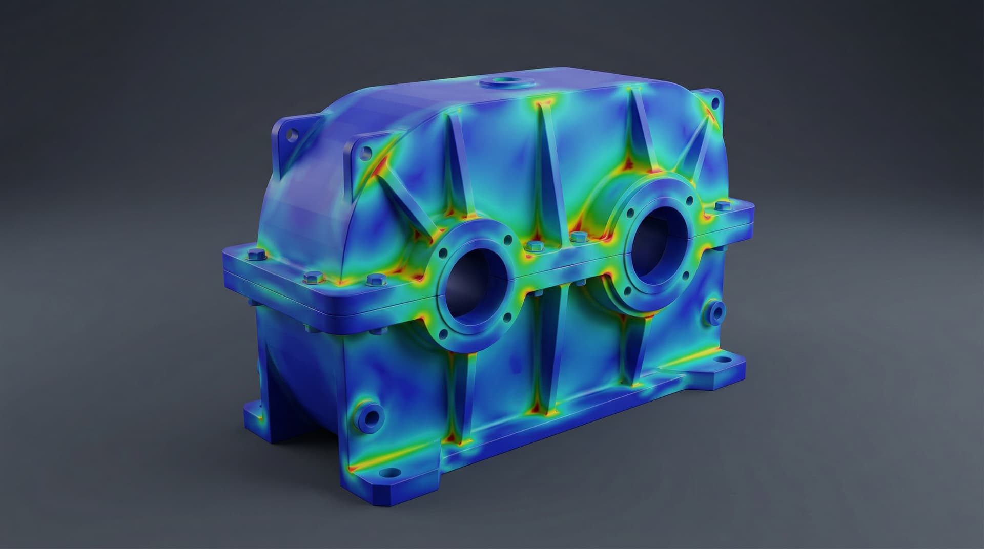
Thermal analysis and CFD simulation of temperature distribution inside an electronics enclosure

Core idea

What this blog covers

Electronics enclosures frequently fail thermal compliance due to compounding packaging constraints: sealed IP-rated housings that eliminate ventilation, high-power compute SoCs and power stages concentrated in small volumes, and poor conduction paths across thermal interface materials. Catching these issues before cutting mold steel is essential.

Main discussion

Why early thermal analysis prevents costly tooling rework

Thermal behavior cannot be easily patched once enclosure tooling is cut. If an IC overheats during prototype bring-up, adding ventilation holes compromises ingress protection (IP65/IP67), while retrofitting external heatsinks or altering internal ribbing requires expensive injection mold or die-casting tooling modifications. Running CFD thermal simulations inside the early CAD modeling phase allows mechanical and electrical teams to co-optimize component placement, copper plane distribution, and chassis heat dissipation paths while geometry modifications are fast and inexpensive.

Heat source mapping & component junction temperatures

An accurate thermal model begins with an explicit component power map. Key heat generators — microprocessors, SoCs, power MOSFETs, motor drivers, inductors, and voltage regulators — must be defined with their operating wattage and thermal resistance networks (R_theta_JC and R_theta_JB). By applying worst-case operating boundaries (e.g., 45°C ambient outdoor solar loading in Indian summer conditions), simulation predicts exact die junction temperatures (T_j = T_case + P × R_theta_JC) to ensure critical silicon remains safely below manufacturer derating thresholds.

Conduction paths & Thermal Interface Material (TIM) selection

Air is an exceptional thermal insulator with a thermal conductivity of roughly 0.026 W/m·K. Microscopic surface roughness between IC packages and metal enclosures traps air pockets, severely choking heat transfer. We design direct conduction paths using compressible silicone thermal gap pads or phase-change materials with thermal conductivities of 3.0 to 6.0 W/m·K under calibrated compression (typically 20–30% deflection). For high-power processors, dedicated CNC aluminum pedestals integrated into the housing base conduct heat directly to the exterior chassis.

Sealed IP66/IP67 vs ventilated enclosure cooling trade-offs

Cooling strategy depends heavily on the enclosure's environmental rating:

• Sealed Enclosures (IP65/IP66/IP67): Common for outdoor IoT gateways and robotics controllers where dust and water ingress must be prevented. Because air exchange is impossible, heat relies entirely on internal air circulation, radiation, and solid conduction through the chassis walls to exterior cooling fins.

• Ventilated & Fan-Cooled Enclosures: For higher power densities (>50 W), forced convection using axial or blower fans is required. CFD modeling evaluates fan pressure-drop curves, intake filter resistance, and internal ducting to eliminate recirculating eddy dead-zones and stagnant air pockets.

Conjugate Heat Transfer (CHT) CFD simulation workflow

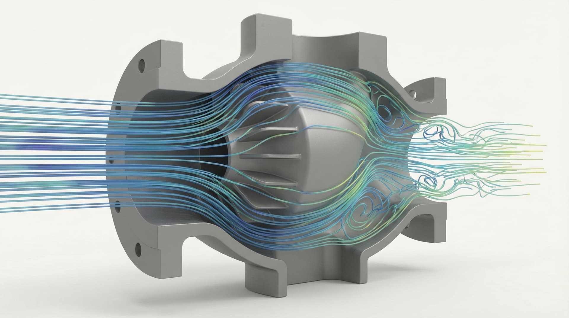
Modern electronics cooling analysis relies on Conjugate Heat Transfer (CHT) in tools like ANSYS Fluent or ANSYS Icepak. CHT simultaneously solves the Navier-Stokes fluid flow equations for natural or forced airflow alongside Fourier's law of conduction within solid PCB layers, component silicon, TIM pads, and metal housing walls. Boundary conditions include ambient temperatures, buoyancy-driven natural convection (Rayleigh number formulation), surface emissivity for radiation exchange, and realistic internal component heat generation.
Tagged

  • Thermal Analysis
  • CFD
  • Electronics Enclosure
  • Conjugate Heat Transfer
  • IP67
  • Heat Sinks
  • ANSYS

Key takeaways

What readers should remember

  • Model solid-fluid Conjugate Heat Transfer (CHT) to couple internal PCB conduction with external convection and radiation.
  • Account for component-level thermal metrics: junction-to-case resistance (R_theta_JC), power dissipation maps, and maximum operating junction limits (typically <= 85°C to 105°C).
  • Bridge component-to-chassis air gaps using high-conductivity Thermal Interface Materials (TIM, 3–6 W/m·K) and dedicated aluminum conduction blocks.
  • For sealed IP66/IP67 enclosures, maximize external housing surface area with optimized convection fin height, spacing, and orientation.

Frequently asked questions

Answers from the work itself.

When should thermal analysis happen in the product design cycle?

As soon as component power budgets and enclosure geometry are tentatively defined — ideally during initial CAD revisions before tooling release. Catching thermal bottlenecks in software is fast and inexpensive; discovering them during prototype testing requires retooling and weeks of delay.

What is the difference between simple thermal hand calculations and CFD?

Hand calculations using 1D lumped-thermal resistance networks are useful for rough sanity checks of isolated components in open air. For sealed enclosures with multiple interacting heat sources, spatial temperature gradients, fluid buoyancy, and complex internal air convection, Conjugate Heat Transfer (CHT) CFD simulation is necessary for reliable junction temperature predictions.

How do you cool a sealed IP67 electronics enclosure without fans or vents?

Sealed IP-rated enclosures rely on solid conduction cooling. Heat from high-power components (SoCs, power stages) is transferred directly into the aluminum chassis via compressible thermal interface materials (TIM gap pads) or copper heat pipes, where external heatsink fins dissipate the energy via natural convection and radiation.

Related reading

Keep going on simulation.

Continue exploring

Related services and proof points

Explore our core engineering capabilities and verified hardware case studies related to this technical domain.

Engineering Consultation

Working on a similar engineering problem?

Share your technical specifications, prototype requirements, or CAD models with our engineering team. NDA support is available where required before confidential CAD exchange.