Kinematic configuration — 6-DOF Articulated vs SCARA vs Cartesian
The kinematic topology dictates workspace reach, dexterity, and structural rigidity. A 6-DOF articulated arm (spherical wrist arrangement) provides complete 3D position and orientation (x, y, z, roll, pitch, yaw) within an envelope of 600–1200 mm reach, making it ideal for machine tending, complex inspection, and bin picking. When tasks are strictly horizontal/planar pick-and-place with vertical insertion (e.g., PCB assembly or packaging), a 4-DOF SCARA offers 2–3x higher cycling speeds and lower bill-of-materials cost with simpler Z-axis ball screw actuators. Cartesian/gantry robots provide superior structural stiffness and sub-tenth-millimeter repeatability across large rectangular envelopes but lack angular articulation.
Joint torque budgeting and sizing calculations
Sizing robotic joint actuators requires calculating both static gravity holding torque and dynamic acceleration torque under worst-case extended cantilever reach:
1. Static Holding Torque (Worst Case): T_static = Σ (m_i × g × r_i) + (m_payload × g × L_reach), where m_i is link mass, r_i is link center-of-mass distance, and L_reach is maximum horizontal extension.
2. Dynamic Acceleration Torque: T_dynamic = I_reflected × α_joint, where I_reflected is the effective rotational inertia of links plus payload reflected through the reduction ratio, and α_joint is desired angular acceleration (typically 2–5 rad/s² for industrial pick-and-place).
3. Total Peak Joint Torque: T_peak = (T_static + T_dynamic) × S_f (where safety factor S_f is typically 1.3–1.5 to account for friction, windage, and cable harness resistance).
For a 5 kg payload arm with 850 mm reach, base (J1) and shoulder (J2) joints frequently demand 120–220 Nm of peak torque, requiring high-ratio gear reducers (50:1 to 100:1).
Gearbox, motor, and bearing selection for zero-backlash joints
Joint repeatability and stiffness depend on three integrated mechanical components:
• Gearbox Technology: Harmonic drive (strain wave) reducers are preferred for wrist joints (J4–J6) due to their high power density, compact coaxial packaging, and zero backlash (<1 arcmin). For shoulder and elbow joints (J2–J3) subject to shock loads, cycloidal reducers offer 3–5x higher shock resistance (up to 500% momentary overload capacity).
• Motor Integration: Frameless brushless DC (BLDC) torque motors integrated directly into CNC aluminum joint housings reduce axial footprint compared to coupled NEMA-frame motors, enabling hollow-shaft wiring routing through the joint center.
• Bearing Support: Crossed roller bearings (CRBs) handle combined high radial, axial, and tilting moment loads in a single compact footprint, eliminating the need for bulky back-to-back angular contact bearing pairs.
Closed-loop feedback & dual-encoder architecture
To eliminate mechanical backlash and link elasticity from the position loop, high-precision arms employ a dual-encoder architecture: an incremental optical/magnetic encoder on the motor shaft provides high-frequency velocity feedback for Field-Oriented Control (FOC) current commutation, while a high-resolution 17–20 bit absolute magnetic or optical encoder on the gearbox output shaft directly measures true link position, eliminating the need for mechanical homing routines after power cycles.
Structural stiffness, FEA simulation & vibration mitigation
Link deflection directly degrades tool center point (TCP) accuracy. We design structural link segments using rib-reinforced thin-walled 6061-T6 aluminum or high-modulus carbon fiber tubes. Prior to CNC machining, in-house FEA structural stress and modal frequency simulations verify that the first natural resonant frequency of the fully extended arm remains comfortably above 25 Hz to prevent controller instability and oscillation during rapid trajectory stops.
Software stack — ROS 2, MoveIt 2 & ros2_control
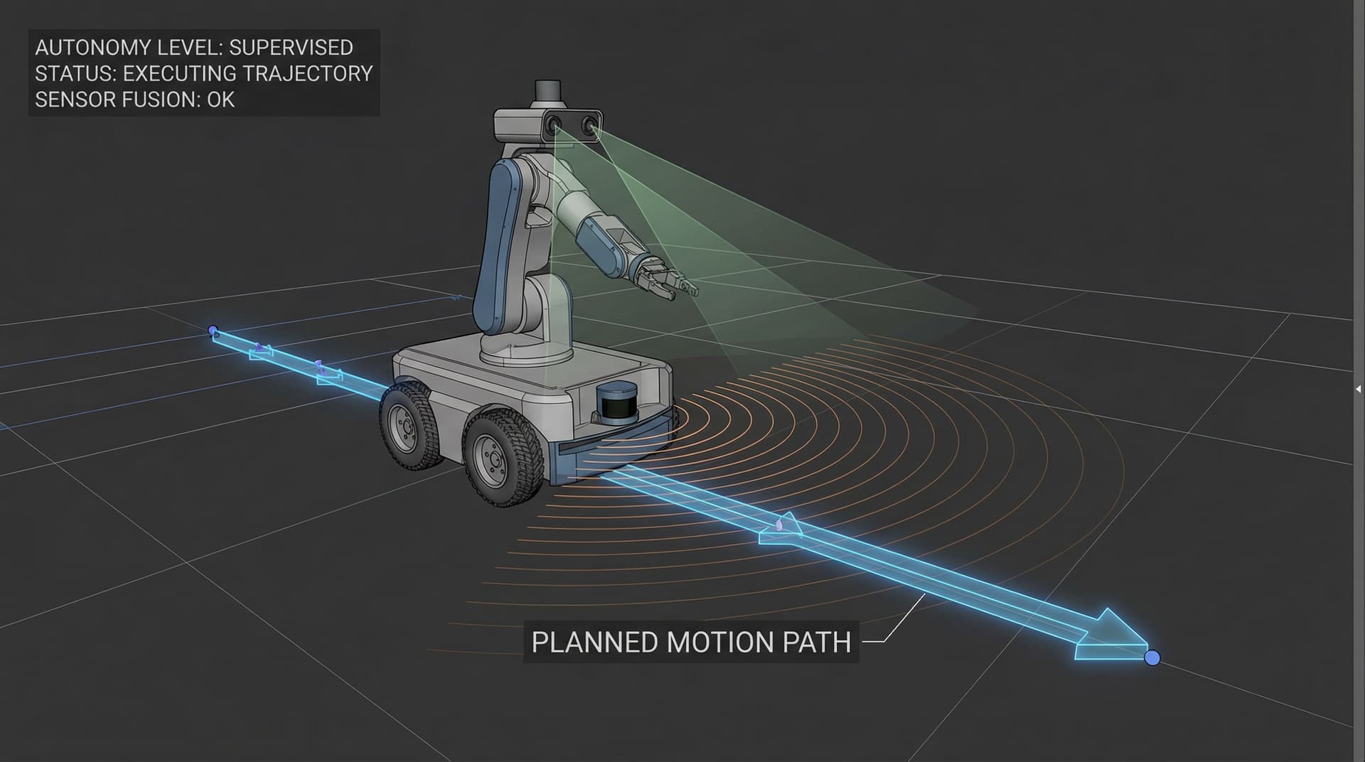
We construct a verified URDF/Xacro kinematic description with accurate inertia matrices, mesh collision models, and joint limit boundaries. Motion planning is powered by MoveIt 2 utilizing OMPL (RRTConnect / PRM) or Pilz industrial motion planners for deterministic Cartesian trajectories. The low-level interface uses ros2_control communicating over CANopen / EtherCAT at 250–1000 Hz, with full kinematic verification in Gazebo and NVIDIA Isaac Sim before powering physical joints.